
About the group of SATCOM satellites
A group of SATCOM satellites is located in geostationary Earth orbit. The first of the satellites was put into orbit in the 1970s and was actively used by the US Navy, but later it was written off as unnecessary and unreliable.
Satellites are transponders — transceivers that transmit what their receivers received without converting the received signal. That. if a signal with FM modulation is transmitted to the satellite, then the transmitted signal will also be with FM modulation; if broadcast in AM, AM will be broadcast; if transmitted with GMSK, GMSK will be broadcast.
The power of transmitters on satellites is 50 W. The channel bandwidth is either 5 kHz or 25 kHz. Transponders with a channel bandwidth equal to 25 kHz, respectively, will be able to transmit several narrowband signals in parallel. Then. on one channel of the transponder it is possible to “place” several, for example, speech (voice) channels that do not interfere with each other.
Equipment for work via SATCOM satellites
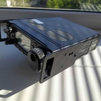
For reception, a radio receiver (radio station) in the range of 200-300 MHz and an antenna are required.
The signal level received by such a simple antenna can be about S5-S7, which is very already very good. Naturally, the quality of the signal depends very much on the latitude where the reception takes place.
A Yaga-type antenna can be used as an antenna. For reliable operation, you need an antenna of the cross-yaga type, or a spiral one with circular polarization.
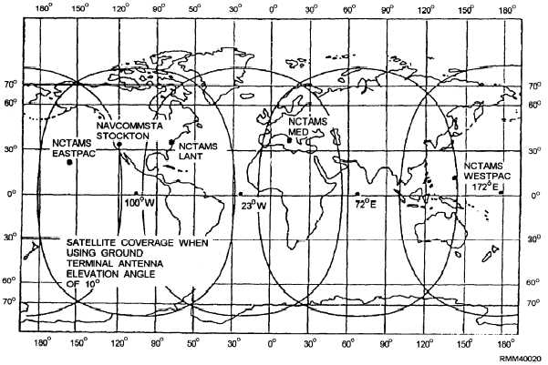
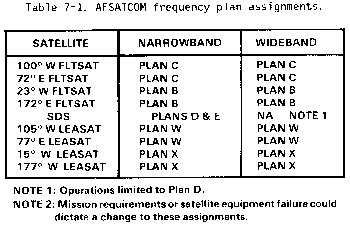
FLTSATCOM There are four FLTSATCOM satellites in service.These satellites are positioned at 100° W, 72.5° E, 23°W, and 172° E longitudes. They serve the Third, Sixth,Second, and Seventh fleets and the Indian Ocean battlegroups. These four satellites provide worldwide coverage between 70° N and 70° S latitudes (figure2-5).